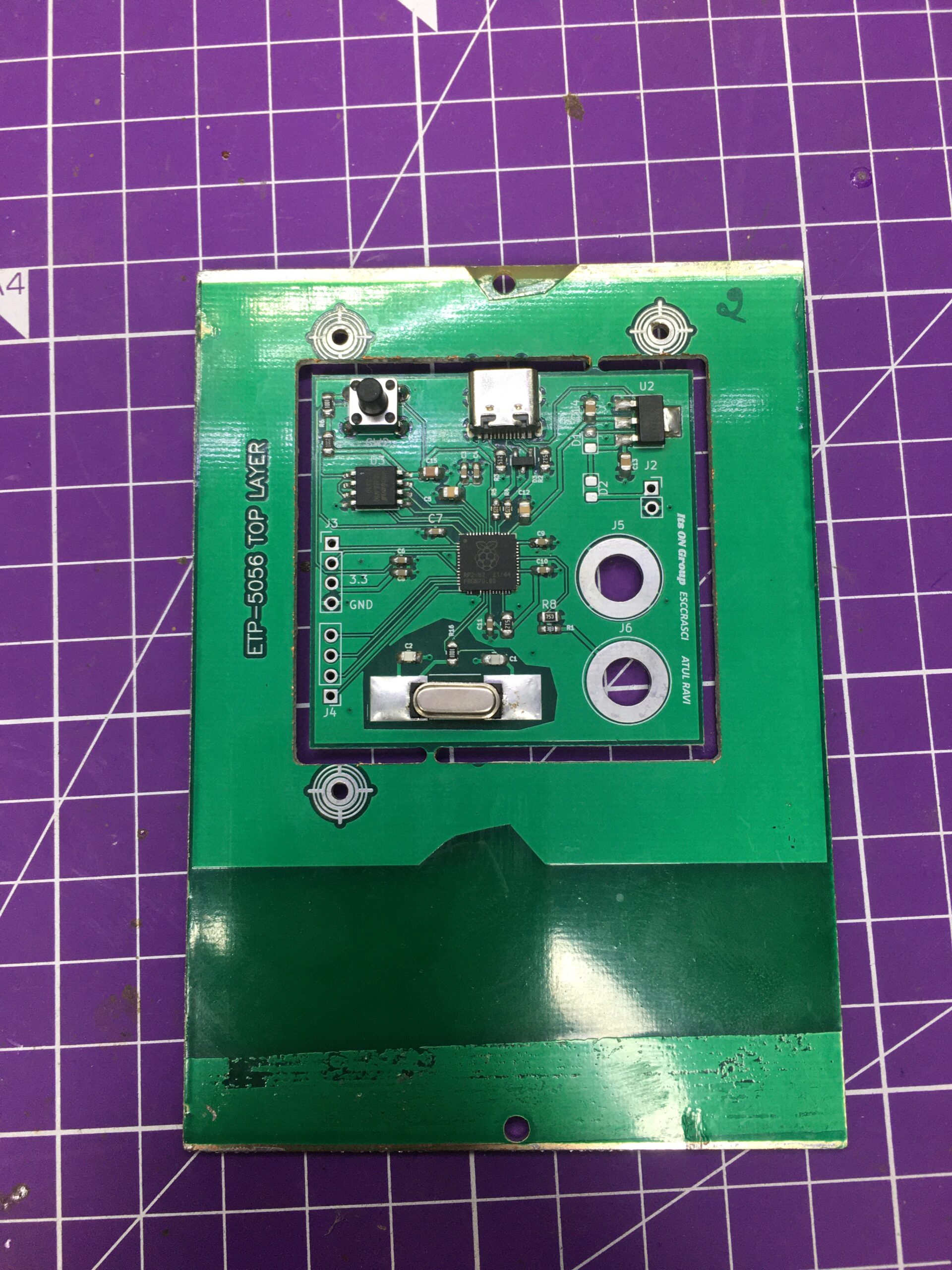
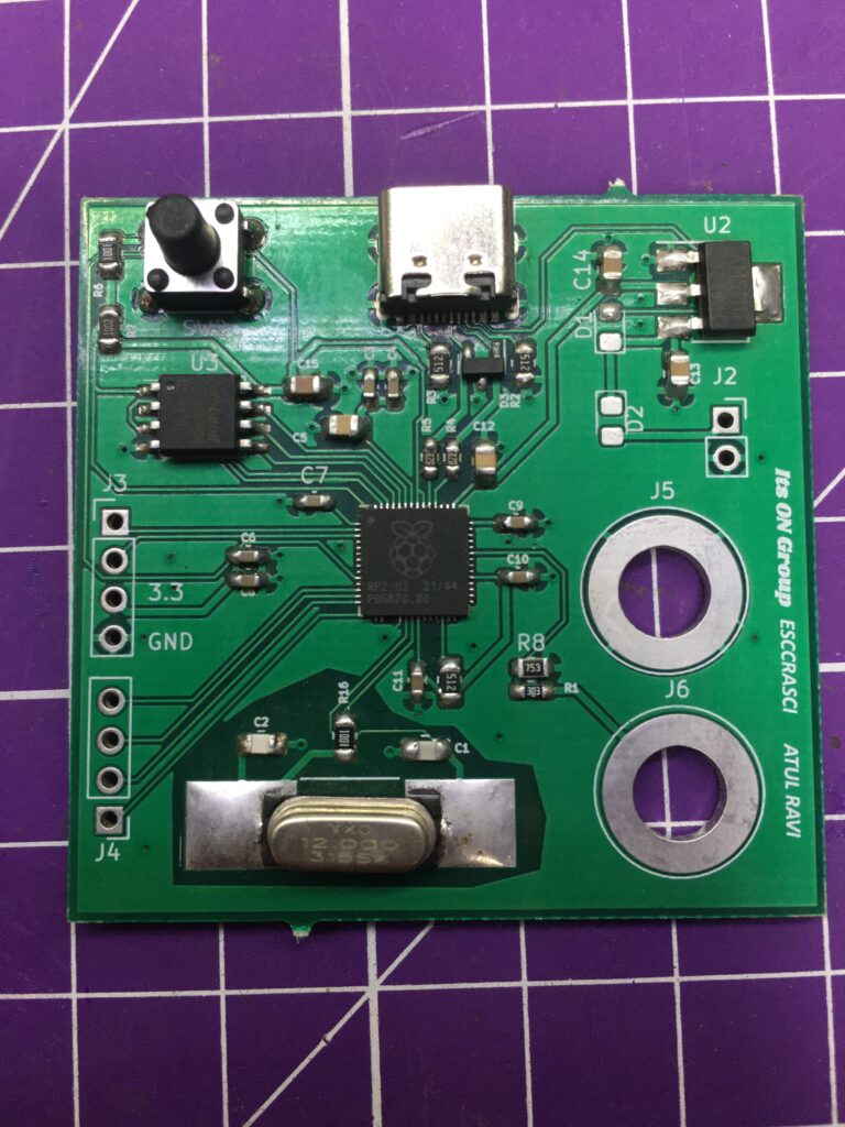
In October, I decided to build my project using the RP2040 chip made by Raspberry Pi. So, I decided to make the Voltmeter project I built a few months prior.
The design was sent to fabrication at the start of November and came to my hands at the end of December. But it was when I received the board, I found a fundamental flaw. After nearly 2 days of debugging, I found that the USB C connector was missing 2 crucial connections. Luckily, I was able to replace it with a USB mini-B connector which led to the board working comfortably.
The debugging process has been documented fully on X where I took the help of Jeremy Cook (@jeremyscook) and Shawn Hymel (@shawnhymel) to debug. Luckily, the board was working mostly from the factory except for that one aspect. The thread can be read by reading the replies to the thread below.
I had the board made fully in India at Lion Circuits (lioncircuits.com) with parts from local suppliers (Ktron.in and evelta.com). However, due to some unforeseen circumstances, the ship time was delayed from Dec 6 to Dec 29. So, I spent NYE debugging the board mostly which proved to be eventful.
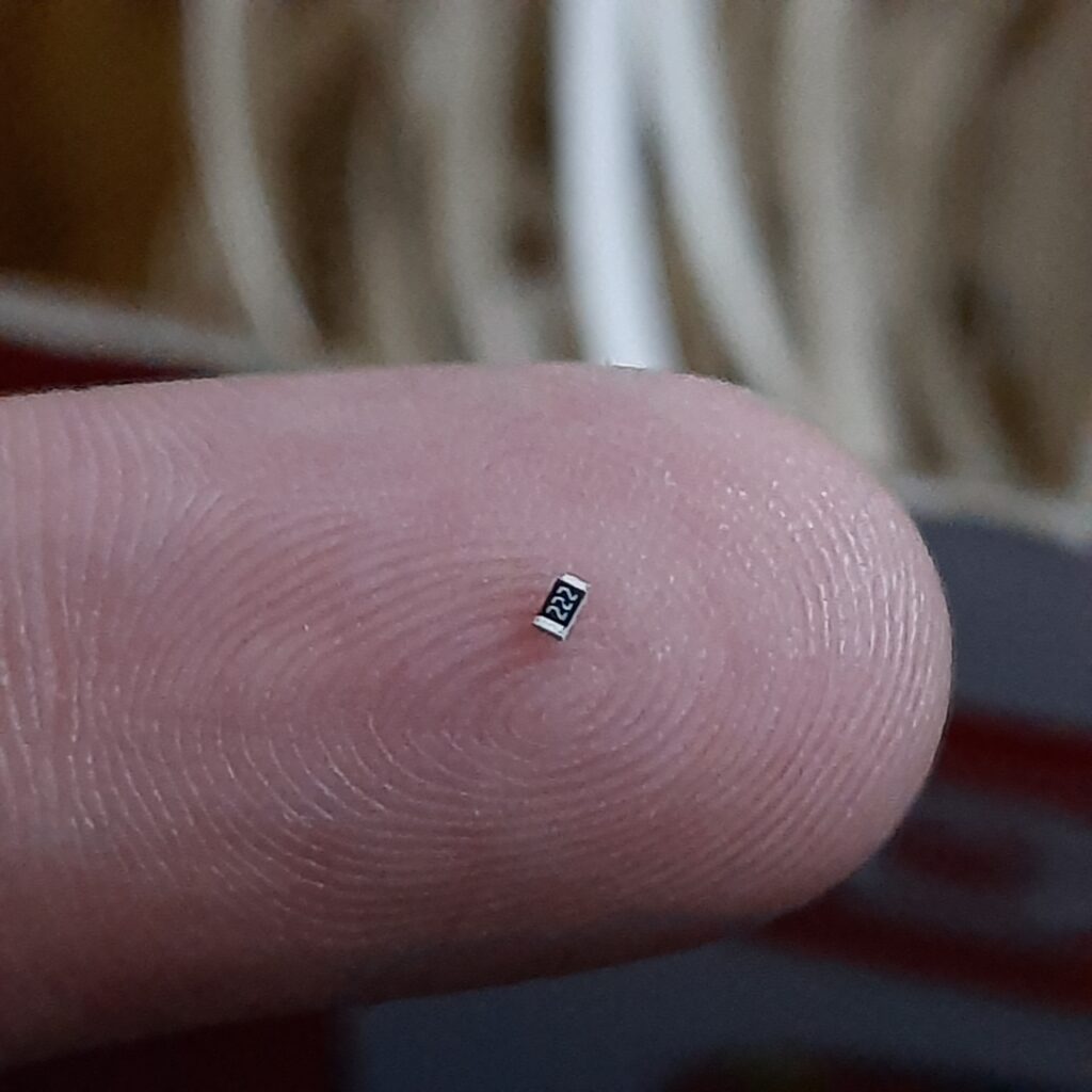
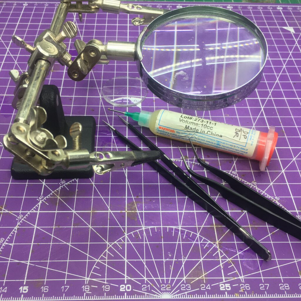
Most of the parts are 0603 and 0804 since soldering them is not tough. But I did struggle a bit initially with 0403 because of their size. But a lot of Amtech Flux and some tweezers saved the day.
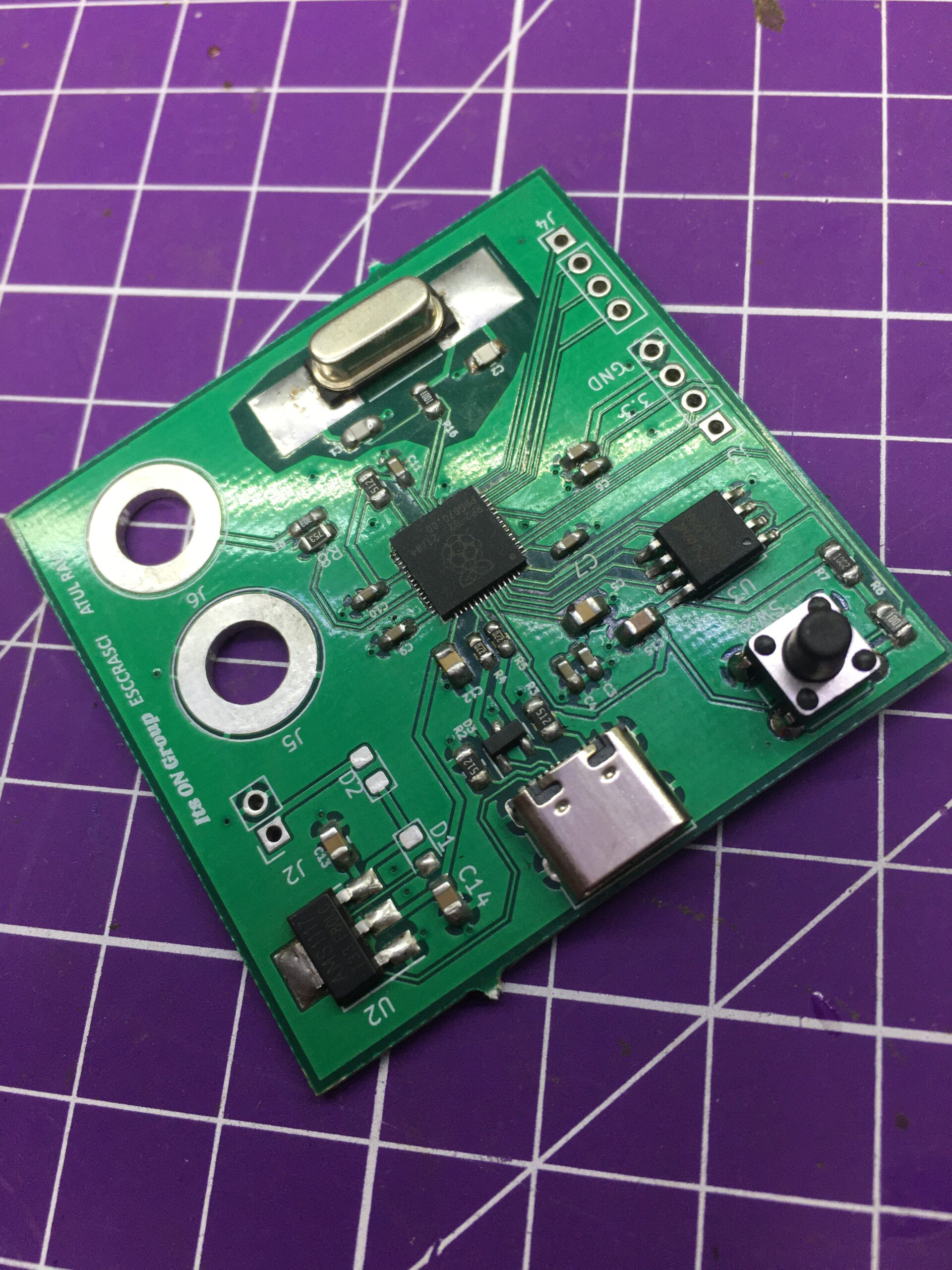
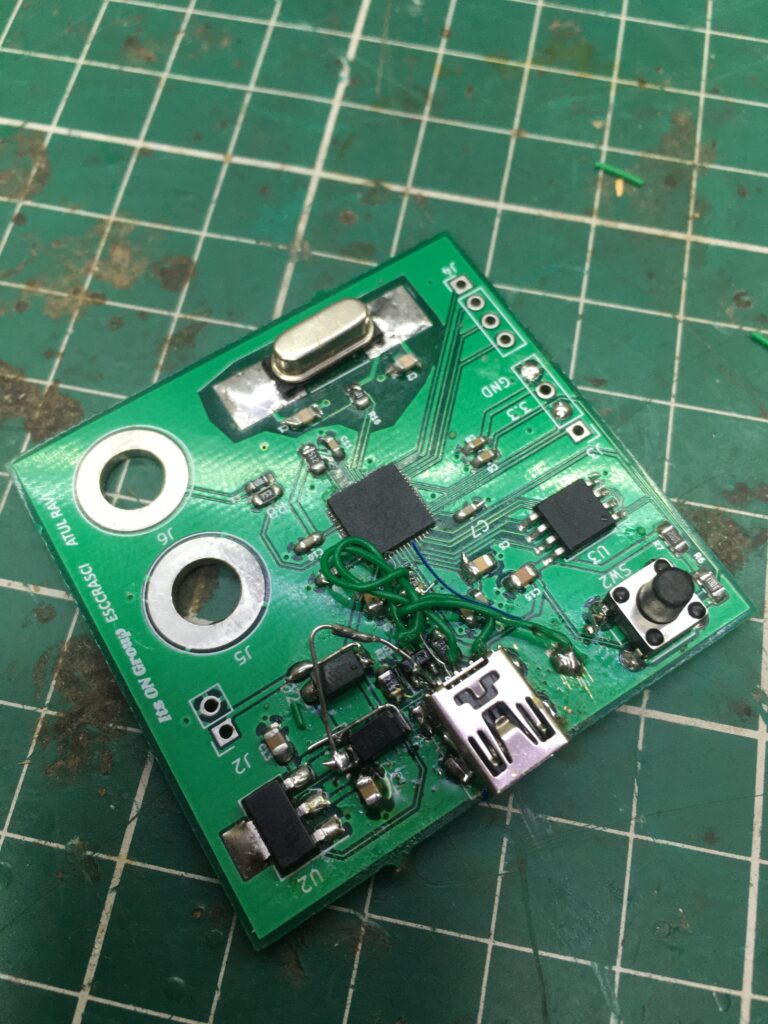
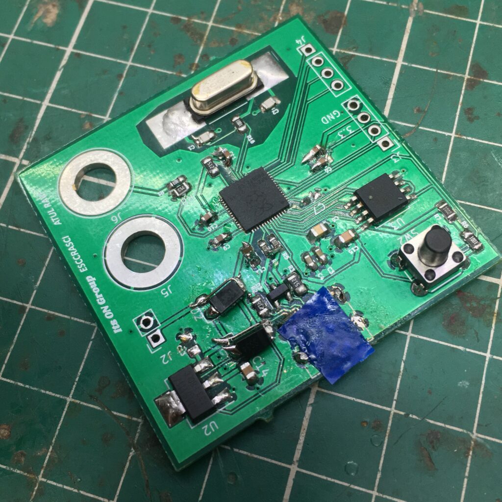
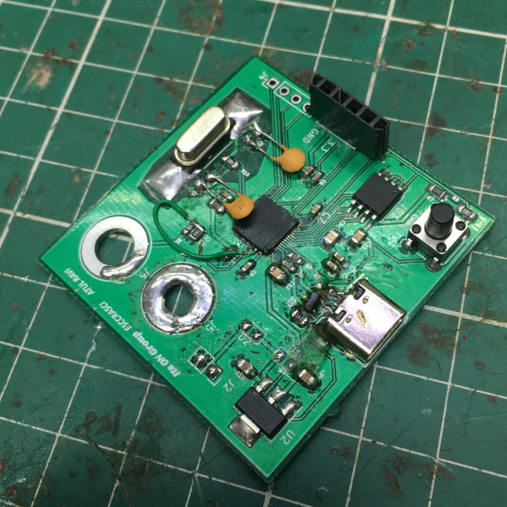
The boards are of excellent quality to feel and use. But because of all the bodges required, it looks a bit odd after the changes.
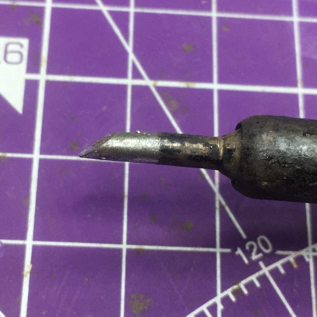
I say with immense pride that I did the SMD rework with the help of the cheap Helping Hand tool that is available for a few hundred INR (a few dollars) and did not rely on a single microscope. And I used a spade bit on my iron for the rework. Of course, with a better tip and some more optical devices, I could’ve maybe done a neater solder job. But I am extremely happy with the output.
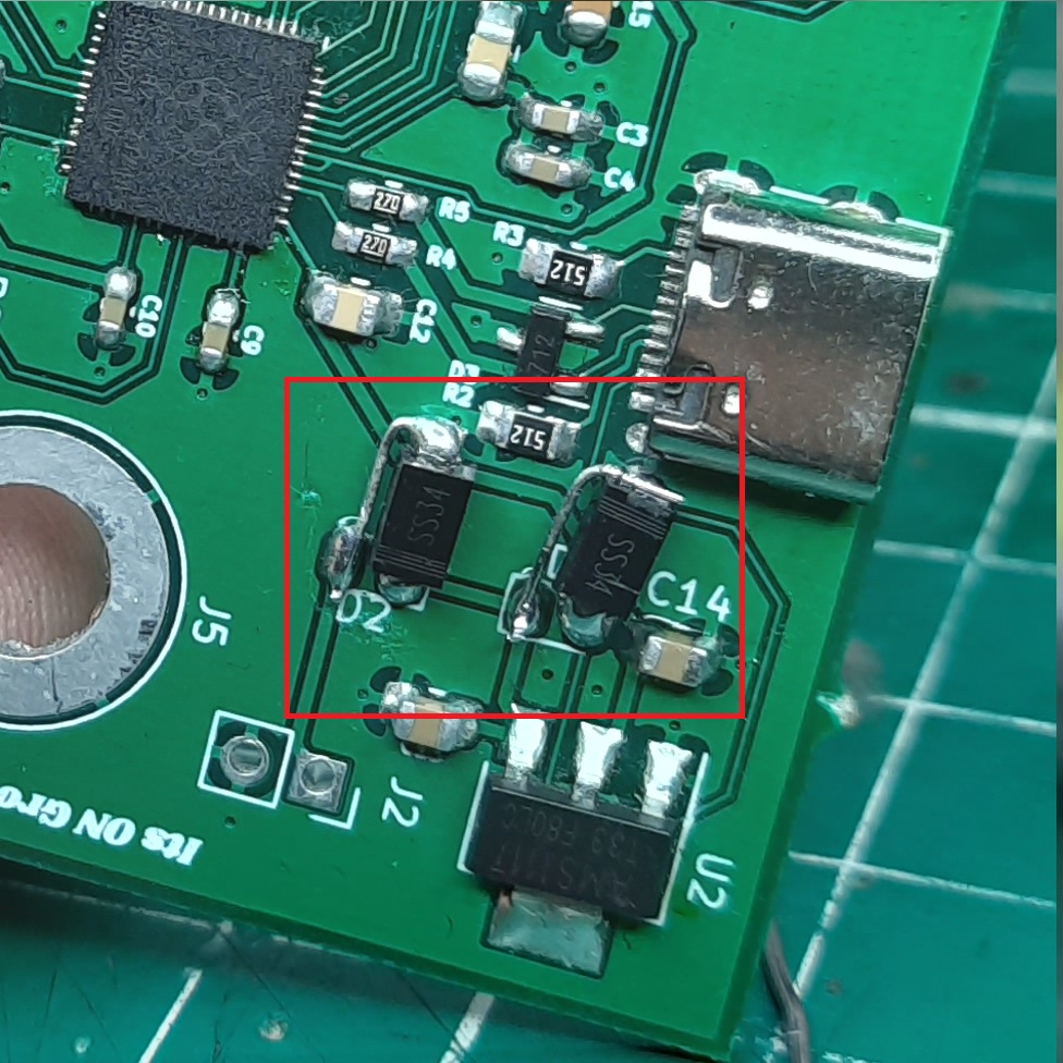
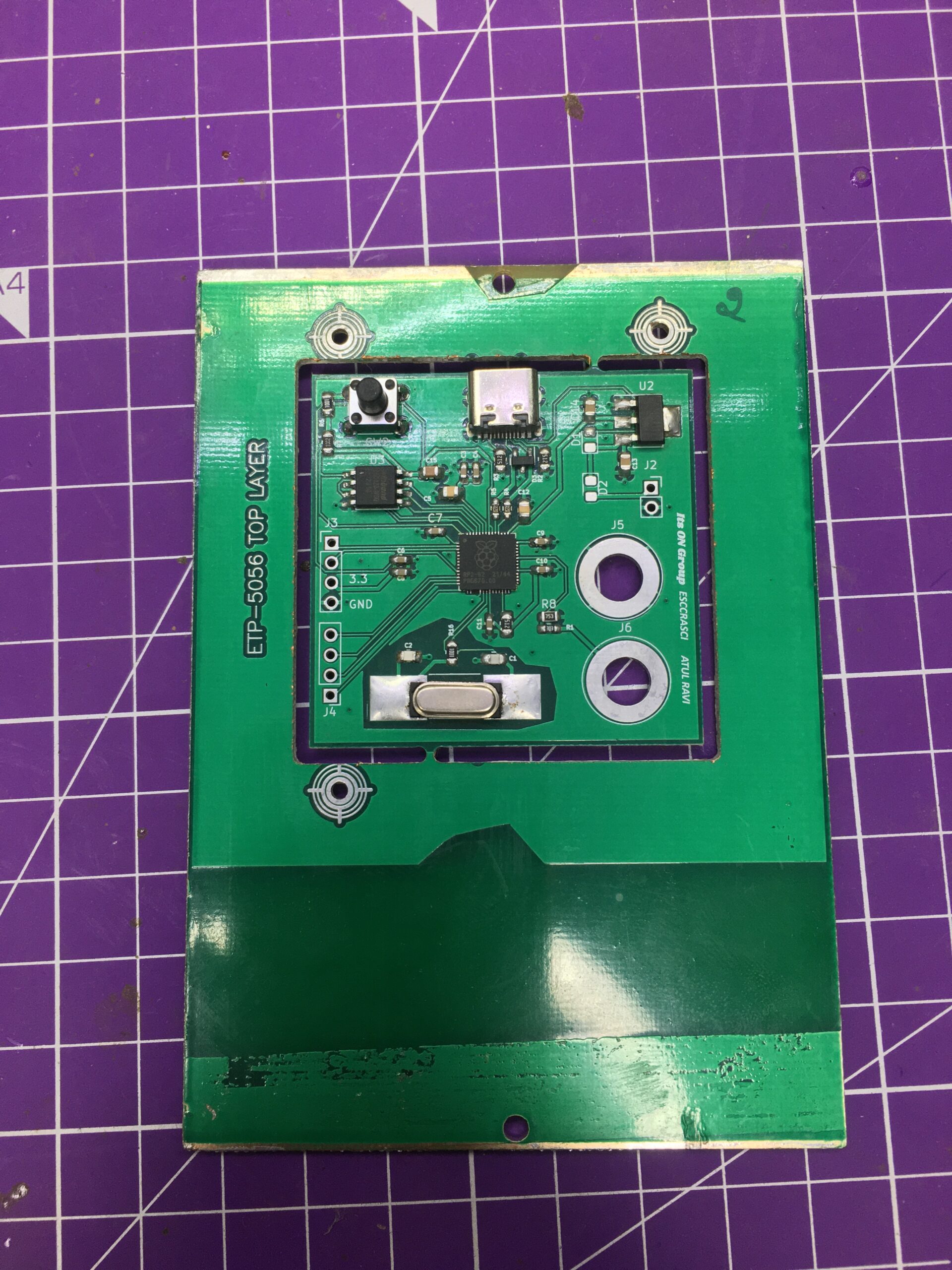
The boards were shipped to me semi-panelized since they were assembled at the fab. However, due to a small issue in the BOM, the diodes were 1206 while 0603 pads were placed and hence, I had to self-assemble.
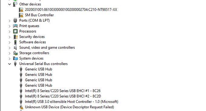
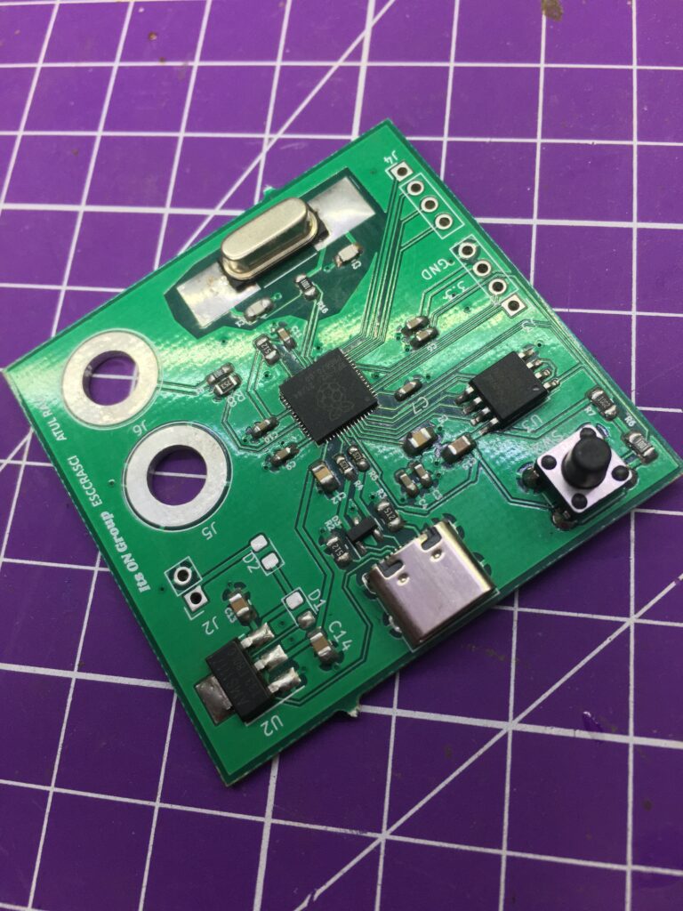
The day I received the boards, I did the first thing of plugging the board into a current meter and confirming that it does not draw 1AmP. Which it did not luckily. So, I plugged it into my PC only to find that Windows failed to recognize it. So, I kept unplugging and re-plugging while subconsciously changing the direction of the USB C cable. (This point proves to be important further on).
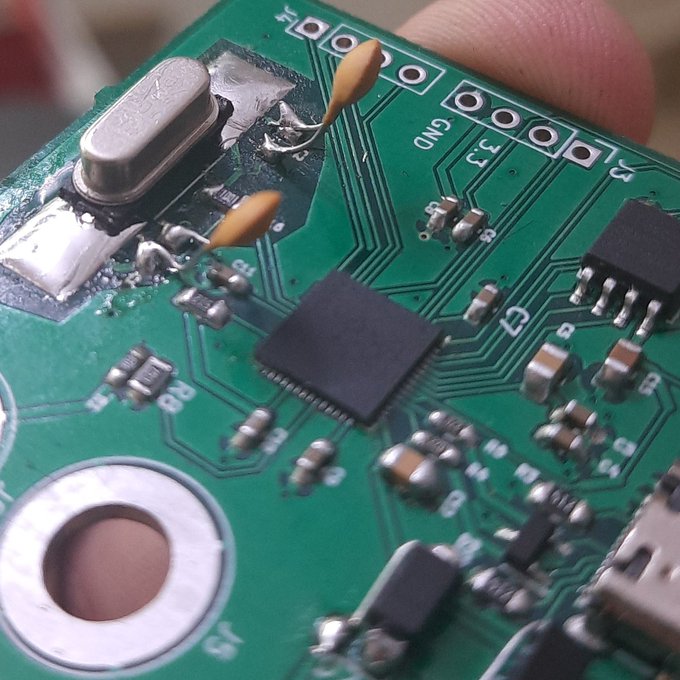
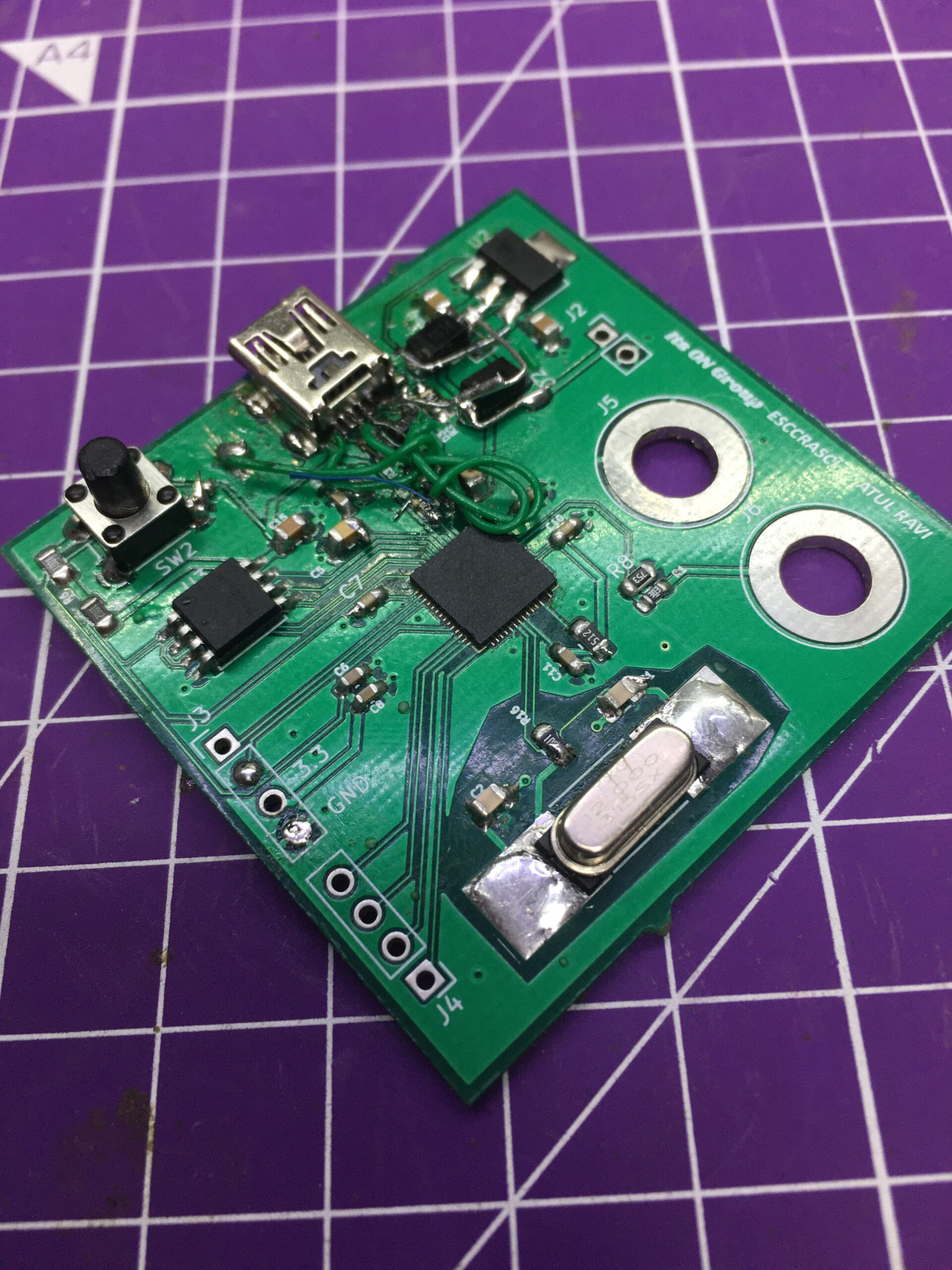
I also found that every time I touched the oscillator windows would give the “Windows did not recognize the last device plugged in” error which is what kept me in a confused state for a while.
Suspecting the Capacitor values of the Oscillator were wrong, I replaced them with 15pF caps after going through the article from Adafruit on choosing correct capacitors for the oscillator. But this failed to fix the issue.
After some discussion in the EEVBlog forum, I decided to solder 2 wires to the SWD and SWC pins for debugging. In hindsight, I made the mistake of not mapping those pins out to a header on the PCB. And I could’ve saved a lot of time. The board was recognized by OpenOCD while I used another Pico board as the debugger. So I ruled out the Oscillator error. You can read through the whole Forum thread here: Issue building custom board with RP2040-eevblog
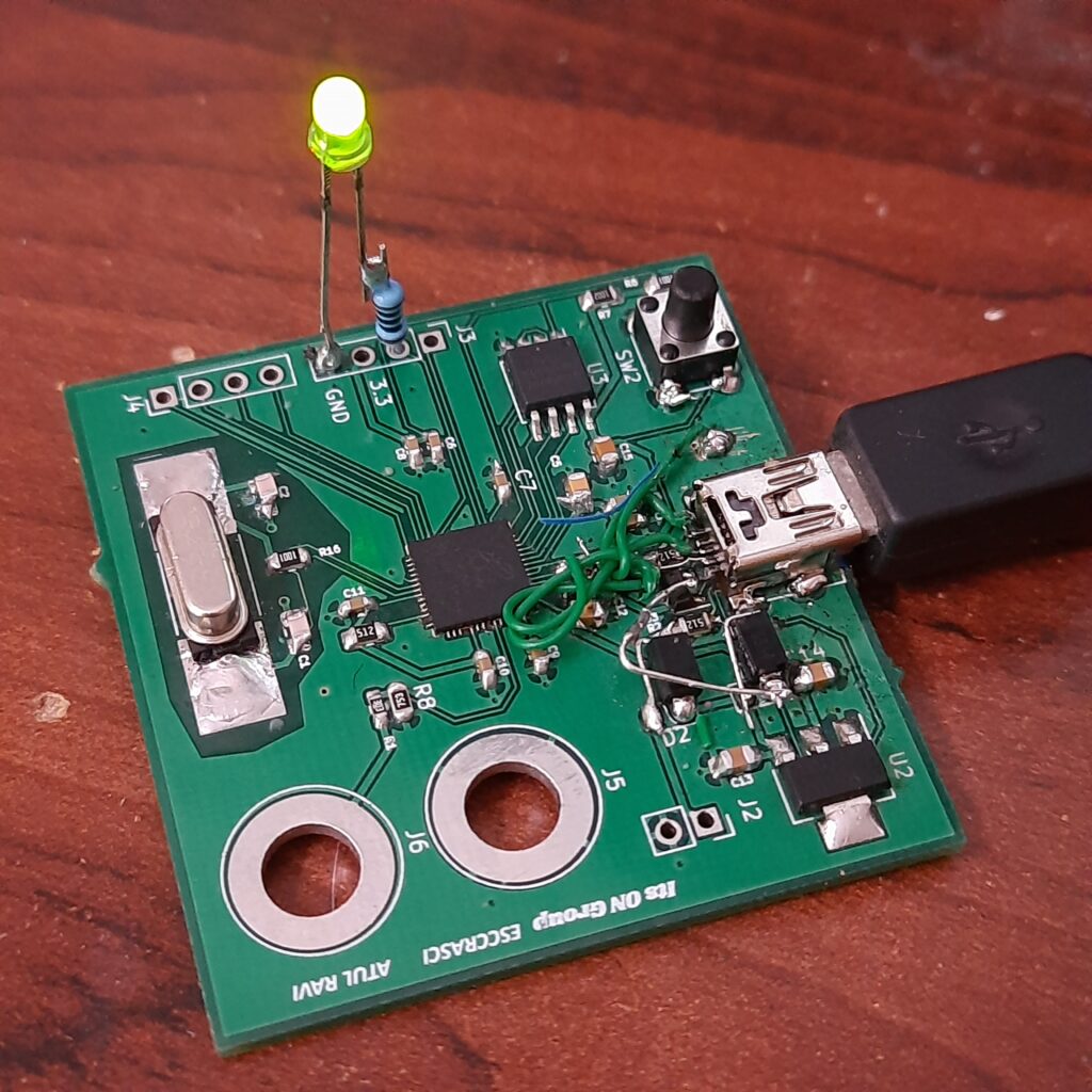
So, after more discussion, I decided to remove the USB C port completely and hard-soldered a USB Cable directly. And at-last, it worked. At this point, I was exhausted and wanted to try other parts of the board and see whether they worked. So, I added Circuit Python to it and ran the obligatory blink sketch with the Mu editor, and the LED Worked.
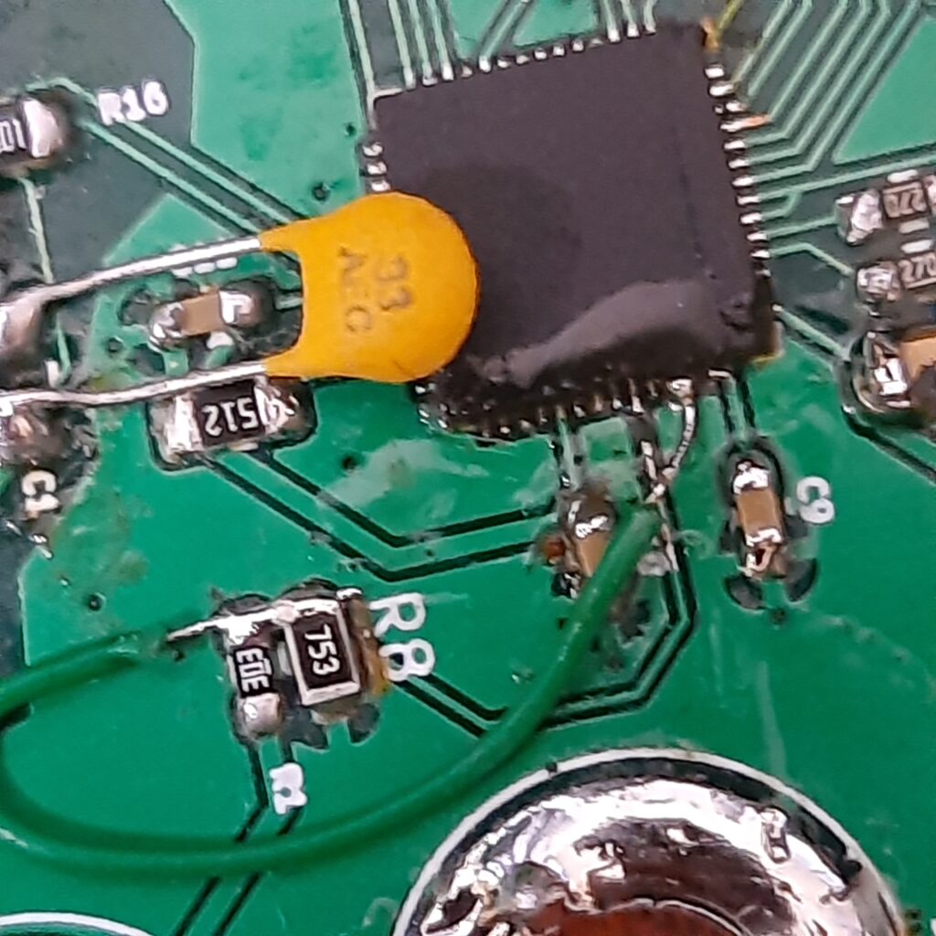
This made me want to test the voltmeter half of the board. So, I uploaded the code from my GitHub Repo and replaced the voltage divider Sens pin port in the code. (GP25). But when the code was uploaded, the board started to misbehave significantly whenever I tried to access the serial monitor. Upon checking, I found that GP25 is the reset pin, so I had to Bodge the divider to GP27. And now that started to work as well! And in case you are curious about the Voltmeter project, you can read more about it from my GitHub repo here: GitHub – atulravi/virtualmultimeter
Now with a newfound confidence, I started to suspect the USB C circuit. So, I checked to see whether the TVS diode was the issue. But on a hunch, I decided to turn the USB C cable around and try plugging it in only to realize that it was the source of error. Suspecting that the Cable was bad, I decided to get a new cable and it failed to work.
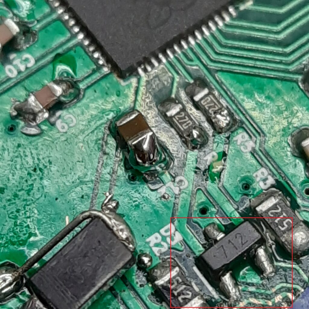
My choice of TVS diode although bad, having no impact because of its voltage rating, ended up working when I did the direct connection. So, I chose to ignore it temporarily.
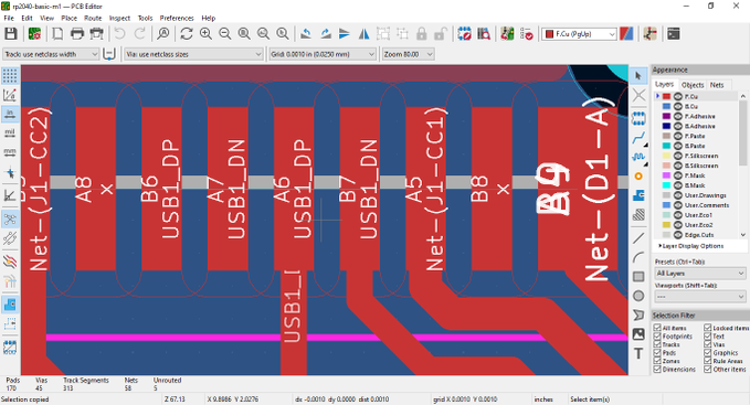
Now, I went back to Kicad and zoomed in on the Connector only to find 2 blue lines across the D+ and D- pins which confirmed that I indeed forgot to connect the data pins. What I did instead was I connected D+ on one side and D- on another side instead of connecting on both sides. This issue is something I was unable to fix since the pins are too small for rework.
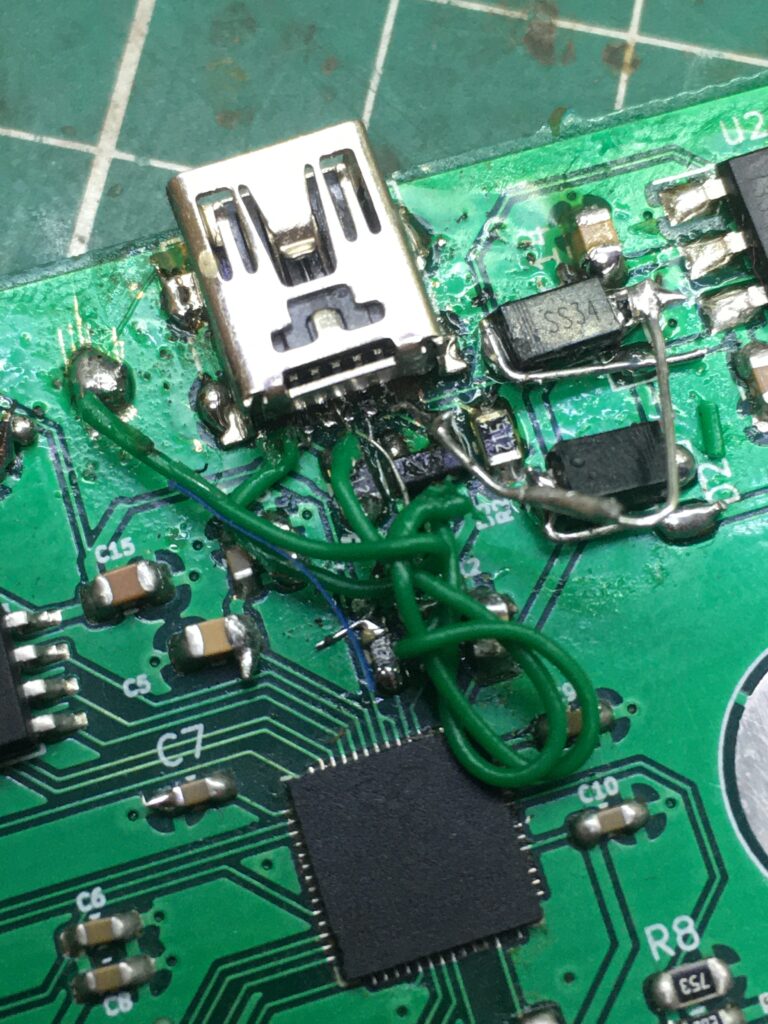
Hence, I decided to replace the USB C connector with a USB mini–B and use a Wire-wrapping wire to connect the pins. Under the B connector, I used some acrylic tape to insulate the part from the exposed traces.

Unfortunately, in the process of removing the USB C connector, I annihilated the pads on the board since I was in a hurry. I should’ve been more careful in hindsight. But the USB mini-B finally worked and hence, I was able to put a full stop to the project.
I learned a lot in the process and the assistance of Jeremy Cook, Shwan Hymel, voltsandjolts (eevblog forum), baldurn, SiliconWizard (EEVBlog Forum) has been paramount and I cannot thank them enough for their support.
Some primary learnings from this build would be:
- Don’t blindly trust DRC and make sure no blue traces appear
- There is nothing wrong in asking for help
- Delays happen in assembly, and planning for the same is required.
- Just because something appears to work, does not mean that it is working.
- There are better ways to plan out the PCB
- Debugging pins must be broken out to save time
- The poor craftsman blames his tools.
I hope this article provided some insight into the building process. If you wish to replicate the same, Gerbers, BOM, Assembly instructions, and design guide are available to download below.
If you liked this article, please feel free to follow me on X (@atulresc) and on Threads (@escrasciyt). Comments are encouraged!
Some Photos of the board.
Leave a Reply