So I have finally finished making the chip after 3, mostly successful attempts.
The thing is that the chip I made follows the principle of a real chip i.e. I mean that it uses transistors as its brain.
It is a single transistor capacitor based IC. It is also called LB103 (3rd version).
What it does is that it blinks the LED based on the voltage and the capacitance. What I did was that I used a capacitor of value 407 microfarad. What I found was that the chip was very bad at blinking the LED accurately. Even a change of 1 volt causes it to stop blinking for ever. Even with my very accurate (sarcasm) power supply, it was a blast trying to make it work. But I did it and recorded my adventure making and trying to use it. More about LB Series can be read at lbseries.esccrasci.in
But I am going describe its construction here.
The materials I used were:
- BC547 (NPN transistor)
- Proto Board
- Resistors
( I am assuming that you have most of the basic components such as a soldering iron and a lead roll.)
Making the chip:
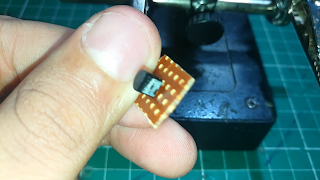
Step 1: So I started with the smallest piece of protoboard I could cut using a knife. Then I cut of the base pin of the transistor. I did that as the base pin is not required for the configuration.
Then I soldered the transistor in place.
Moving on,
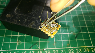
Then I needed to add the legs that made it look like a chip. Before that I would like to tell you that I made a huge mistake when cutting my PCB which will be highlighted by me in the video check it there. Due to which the chip’s legs were not aligned properly and it did not fit properly.
For the legs I used 2 resistors of a type I never used. And then I finished preparing the legs.
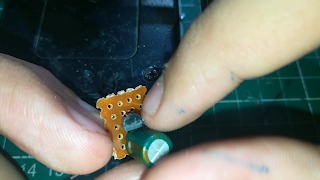
Then came the capacitor. Unfortunately I used a capacitor of the capacity 407. But if you are also going to attempt this, I sincerely suggest that you use a capacitor of value 100 or anything below 400 or a capacitor of capacity 1000. Also get a branded one mostly from Murata or any other established brand. Then I soldered the capacitor in place. In the first 2 iterations I used a defunct brand’s capacitor (capapower) and the chip was very accurate but the transistor was not. So it was still useless as it was equally inaccurate. This time I used some transistors from TI and the capacitor was inaccurate. But I somehow finally got it to work in the end.
This amplifier is extremely easy to make and only costs about 1$ (if the components are purchased in bulk)
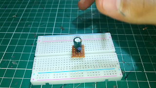
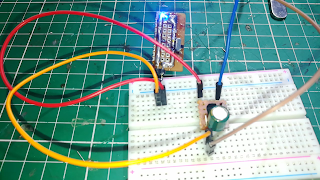
Then I finished the circuit and it was ready. Then came the problem I mentioned before. So I had to adjust the legs of my circuit and then It was ready for testing. During my test I noticed that the chip only worked with 12 volts and it stopped functioning with 13 volts. But I got to work and here it is:
The circuit I used can be downloaded from the link below!
With that this project-info ends.
Link Of the video
You can also download the files from:
Link for the files
And I will also be uploading the gerber files of the PCB and the BOM file with which you can buy the components and also order my PCB of the chip which you can find in my site. (link is given above)
Best of luck, Stay Safe and Have Fun!
Meet you in my next post!
Leave a Reply