Category: DIY
-
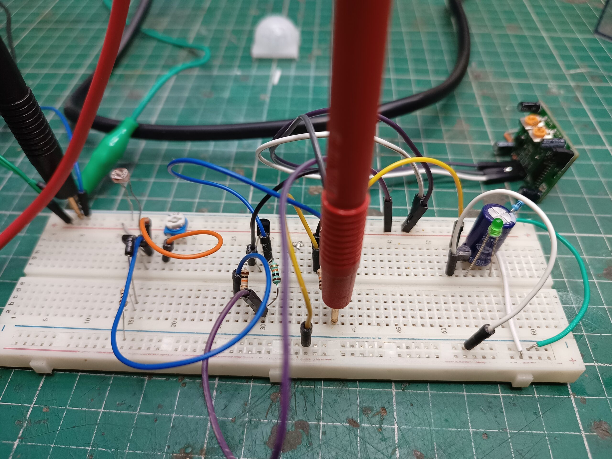
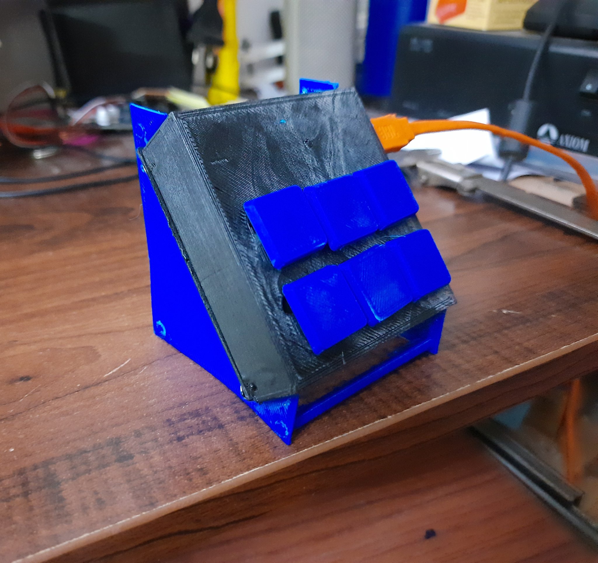
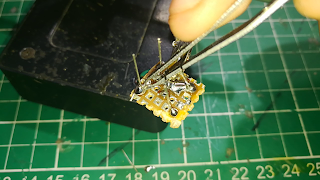
Light that only works in darkness when motion is detected
Learn how to build your own motion detected night light that only works in the darkness with purely discreet components.
-
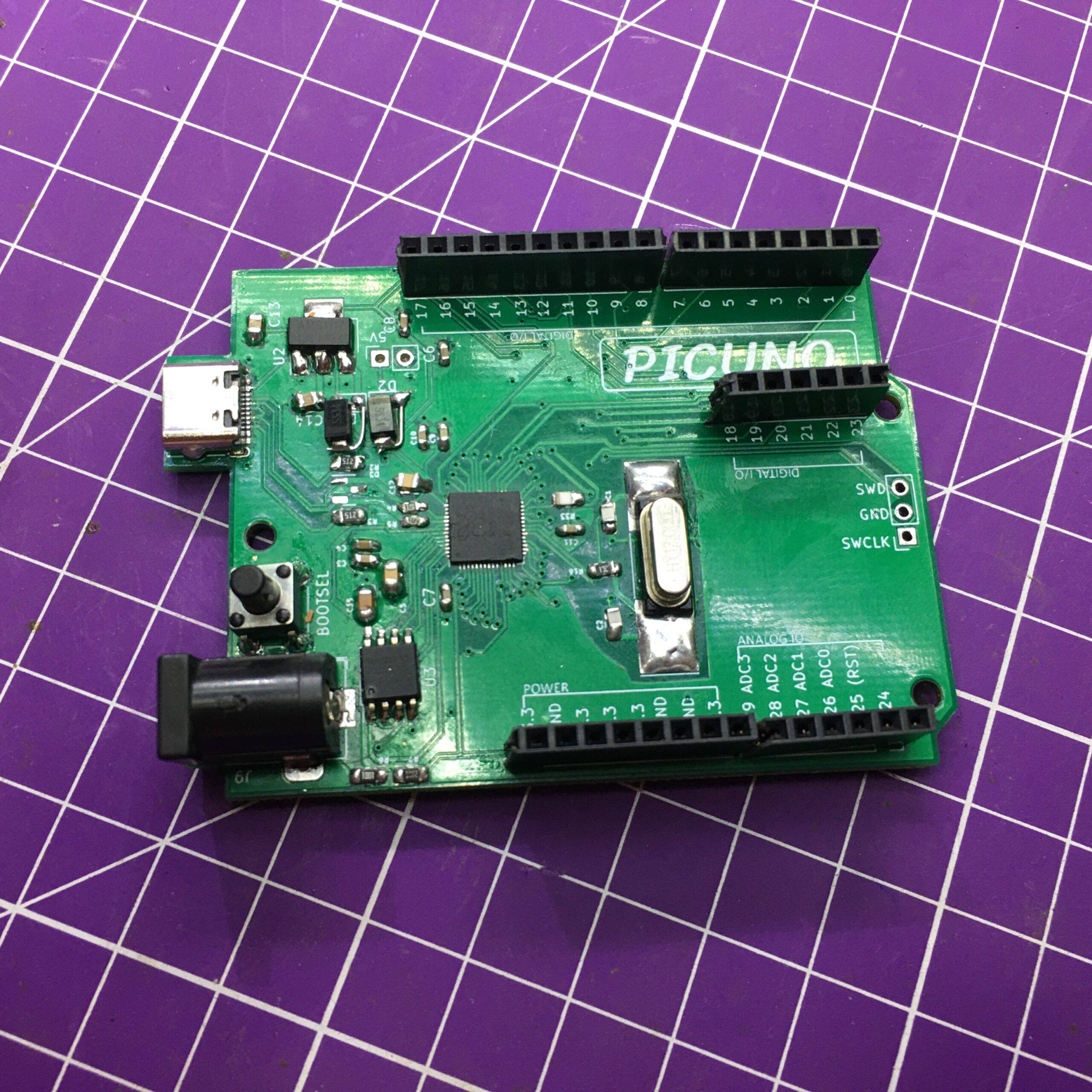
Picuno RP2040
The Picuno is the mix of the RP2040 and the Arduino UNO. A drop in replacement for the UNO compatible with C and python derivatives. Read More!
-
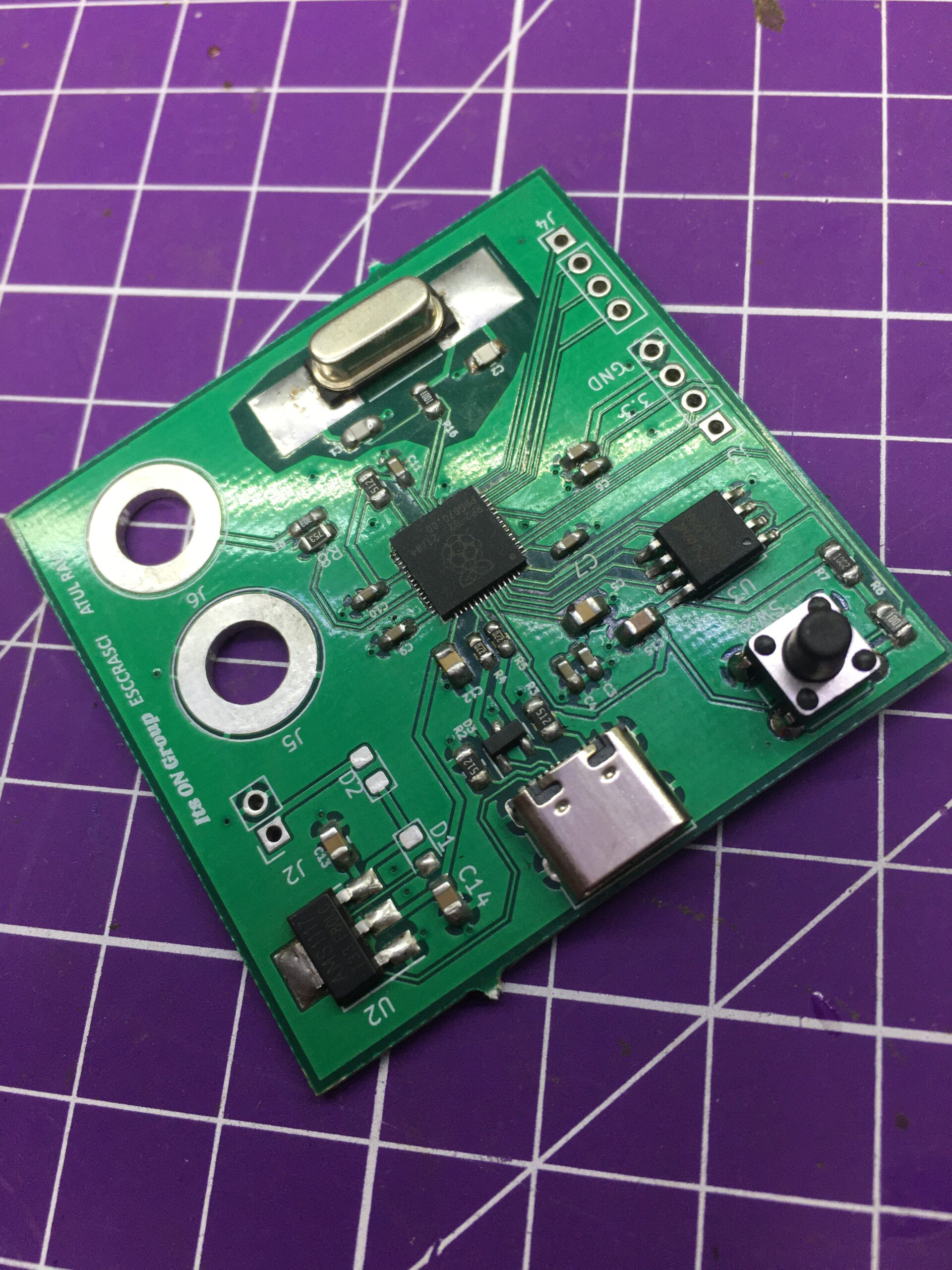
Building a board with the RP2040
This article goes into detail as to how Atul R built his own RP2040 compatible board to go with his voltameter project. Learn to build your own!
-
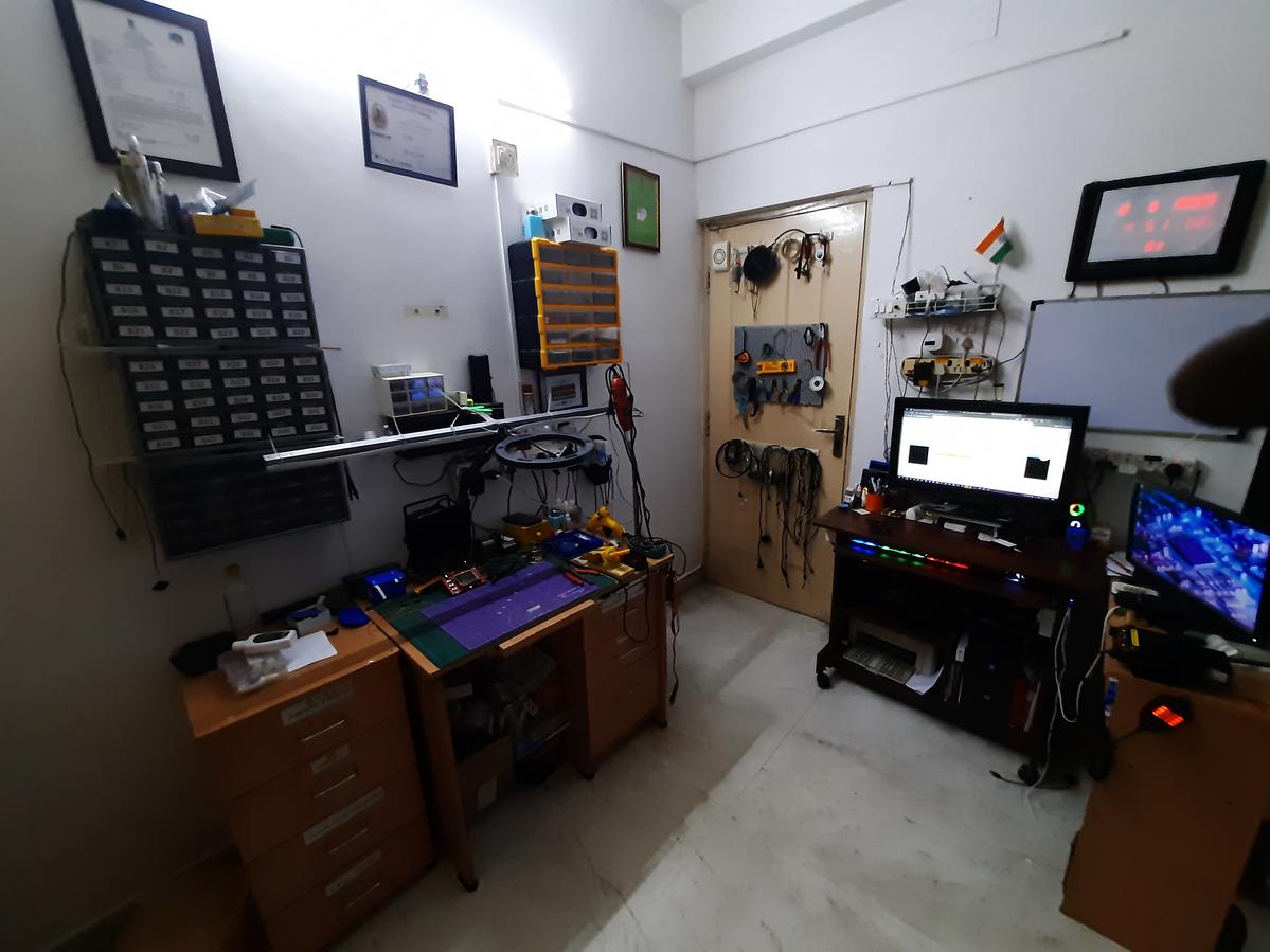
How To Set Up An Electronics Lab
You probably saw a YouTube video on building robots or maybe even a friend of yours has a lab. You want one to practice and make projects. How do you get going with it??
-
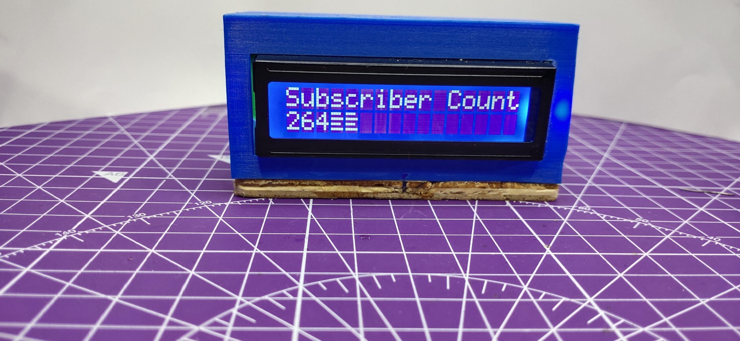
DIY YouTube subscriber counter with LCD and ESP8266
Use an ESP8266 Node MCU And build your own YouTube Subscriber counter with 3D Printing and a very new-age retro aesthetic on your own!
-
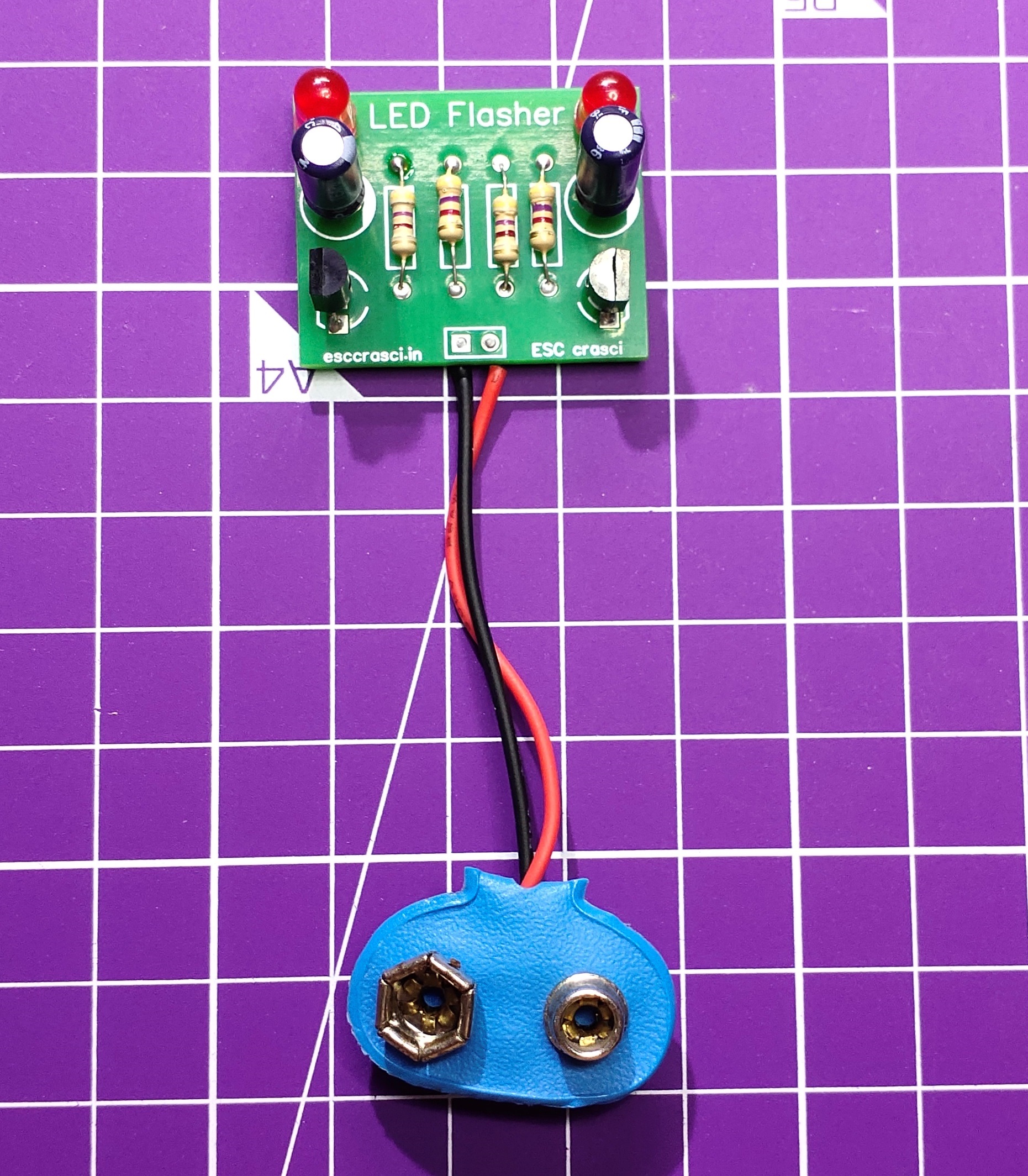
Soldering Kit
This kit is a Dual LED Flasher on a PCB That helps you learn soldering easily. There is no necessity to solder onto perforated boards and spend hours on checking connections. Hence, it helps every beginner learn soldering more easily than ever. Get it here!
-
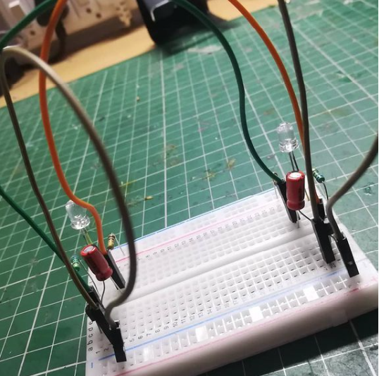
DIY Astable Multivibrator -How I remade the very first circuit I made live
When I first started streaming, I made a dual LED flasher circuit. Unfortunately, I forgot to save the recording of the stream. I decided to make it again and convert my LED statue sculpture into something very interesting.
-
How to make your own ic integrated circuit
So I have finally finished making the chip after 3, mostly successful attempts.The thing is that the chip I made follows the principle of a real chip i.e. I mean that it uses transistors as its brain.It is a single transistor capacitor based IC. It is also called LB103 (3rd version).What it does is that…